
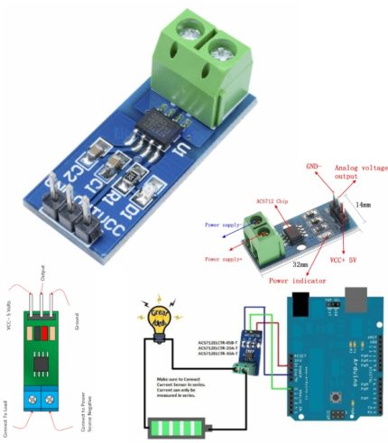
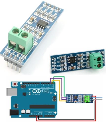
The ACS712 module has two phoenix terminal connectors (green colour ones) with mounting screws as shown above. These are the terminals through which the wire has to be passed. In our case I am measuring the current drawn by the motor so the wires that is going to the load (motor) is passed through the ACS 712 Module. Make sure the module is connected in series with the load and be extra cautious to avoid shorts.
On the other side we have three pins. The Vcc is connected to +5V to power the module and the ground is connected to the ground of the MCU (system). Then the analog voltage given out by the ACS712 module is read using any analog pin on the Microcontroller.
Pin Configuration
Pin Number Pin Name Description
1 Vcc Input voltage is +5V for typical applications
2 Output Outputs Analog voltage proportional to current
3 Ground Connected to ground of circuit
T1 Wire In The wire through current has to be measured is connected here
T2 Wire Out


Reviews
There are no reviews yet.